Adding temperature charting and monitoring to a building air conditioner is easy with the R9 Safezone system. If you already have the R9 system installed, adding this additional feature is very cost effective. A single R9 sensor node can provide 6 channels of operational information, that will help to verify and insure the proper operation of your air conditioning system.
An air-conditioner appliance (AC) is an integral part of modern life. The way our cities are constructed today, in arid and sunny areas, means that an air conditioner is no longer just a luxury. Without a properly functioning AC appliance, a building in the summer months will quickly become un-livable. If your AC unit is like most that are in service, it probably gets minimal maintenance attention, until it stops working. Some disruptions are unavoidable,
but modern sensor technology is beginning to make real-time monitoring of this vital appliance possible. The advantages provided by closely monitoring your AC unit include:
-
-
- Verifying the unit is cooling properly, which relates directly to ongoing operating costs. In winter time, the furnace (warming) operation can also be monitored.
- Early detection of water leaks, and avoiding costly water damage repairs.
- Early detection of issues, which results in better maintenance and repair scheduling, and less down time of this critical appliance.
-
Air-conditioner Cooling Background:
Note that central air-conditioning appliances also provide warming in the winter time (furnace operation). The furnace operation of your AC system is simpler, and will not be explained in detail. Both air conditioner cooling operation, and the R9 Safezone system are covered in more detail, although the same principles apply to furnace operation.
There is plenty of theory related to the operation of your AC unit cooling (thermodynamics, refrigeration cycle), knowledge of which is not necessary for monitoring your air conditioner. It is beneficial to know that your AC unit is expelling heat from inside a building or dwelling to the outside. It does this by compressing, and then cooling a refrigerant outside (condenser unit), and subsequently, expanding and then heating the same refrigerant inside (evaporator unit). The refrigerant is circulating from inside to outside, carrying heat energy to the outside environment. Inside a building, where we will be monitoring, an AC unit is pulling in warmer room air and expelling cooler air that has been blown through the evaporator. So warm air goes in, and cooler air goes out. A byproduct of cooling the air is water condensation which is also routed outside, via the buildings plumbing. The amount of water condensate is substantial, and if it not removed properly, water damage can result.
R9 Monitoring System:
Although it might seem complicated, the R9 monitoring system is very basic and simple in its system architecture. The two devices which comprise the system are the gateway and sensor node. One or multiple sensor nodes are used with one gateway.
The node device gathers information from physical sensors that are attached to it, and then relays that information to the gateway. The gateway device gathers the data from all the node devices that are nearby, and then transfers it to the internet. One, or up to fifty nodes can communicate with a single gateway. This allows several zones or areas to be created where sensor data can be collected by a single node (zone). We are creating one of these sensing zones on an AC unit by attaching a node device to the AC unit. The node device has integral mounting magnets, so it can be easily attached to an AC unit.
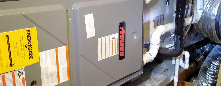
The three pictures below show the AC unit we will be installing a monitoring system on. This unit is located in a building attic, and is two zone system. This means that a single AC unit cools two separate living areas, in this case upstairs and downstairs. There is a single air input which is drawn from both zones, but there are two separate cold air outputs, one going to each individual AC zone. Each up/down zone has its own thermostat, and in this case, the AC unit uses air dampers, or airflow directors to divert more or less air to each zone. In this monitoring system installation, we will measure:
-
-
- The attic ambient temperature
- The AC system input temperature (warm air, drawn from both AC zones, up/down)
- The AC system input air humidity
- The output temperature (cool air directed upstairs)
- The output temperature (cool air directed downstairs)
- Wetness of water collector located below the AC system (leak detect)
-
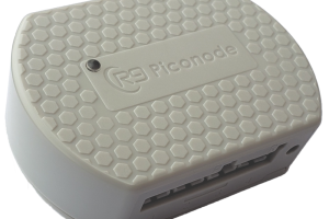
In all the pictures, one SN400 sensor node can be seen attached to the unit. The last picture shows a close-up of the sensor node. Notice that the sensor node is attached to the evaporator (cooler location), and is not located on the furnace section. Although not required, this will give more accurate ambient temperature readings in the winter time when the furnace is running.
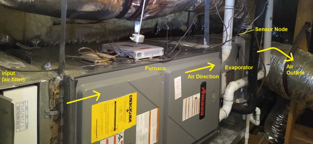
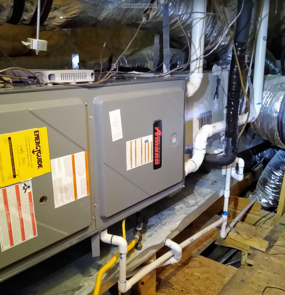

The SN400 sensor node is attached near the middle of the AC unit so probes can be fitted to both the input and output baffles. In addition, the water break sensor is positioned under the AC unit in the drip pan. In the picture, the node is held in place with integral mounting magnets.
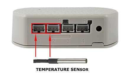
The SN400 node has an internal PCB mounted temperature sensor, and four external sensor connectors. The internal PCB mounted temperature sensor will be used to monitor the ambient temperature of the attic. Each of the four ports will be used to monitor a different parameter of the AC unit. The four external ports are labeled 1,2,3,4 on the SN400 plastic enclosure.
Port 1 and Port 2 will be used to monitor the outlet air temperature for upstairs and downstairs respectively. This requires two separate temperature sensors.
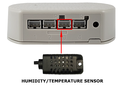
Port 3 will be used to monitor the inlet air temperature and humidity.
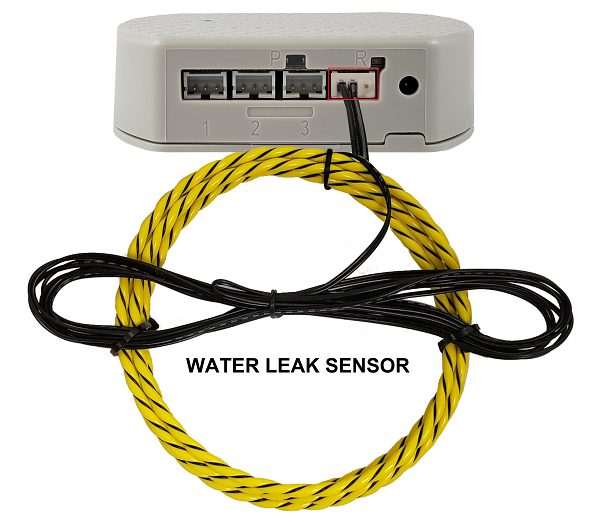
Port 4 will be used to monitor the drip tray for wetness to indicate an air conditioner water leak or drain pipe obstruction. The yellow rope is placed into the drip pan in the lowest position. Note that the yellow rope is the part that can detect wetness. The black wire is leader wire for attaching the yellow water rope to the sensor node. So be sure to place the yellow rope directly where water is anticipated to be detected. Place the black leader wire so it will not get wet from water.
Starting with port 1 and port 2 for the outlet temperatures, use alcohol and a paper towel to clean a small area on each air conditioner duct for accepting foil tape. Then, use an awl or knife to punch a small hole in the alcohol cleaned area on the duct. Both outlet ducts are located on the left side of the air conditioner unit picture.

Insert the temperature probe though the hole so it is just inside the duct, and then carefully tape in place with the foil tape so no air will leak out of the duct. Use about three overlapping layers to prevent air leakage. This is done for both output baffles of the airconditioner, as both upstairs and downstairs output temperatures are measured independently. Refer to the two pictures below.


Next the air input temperature sensor is installed. The sensor used is a dual sensor device that senses both temperature and humidity. For this AC unit, the sensor is placed into the inlet side via the AC air filter door. The door has a deformable gasket which will seal against the cable. Alternatively, a hole could be drilled and sealant used, but in this case placement of the sensor in the air filter door is simple and effective. The cable is placed so it is flat against the deformable gasket.
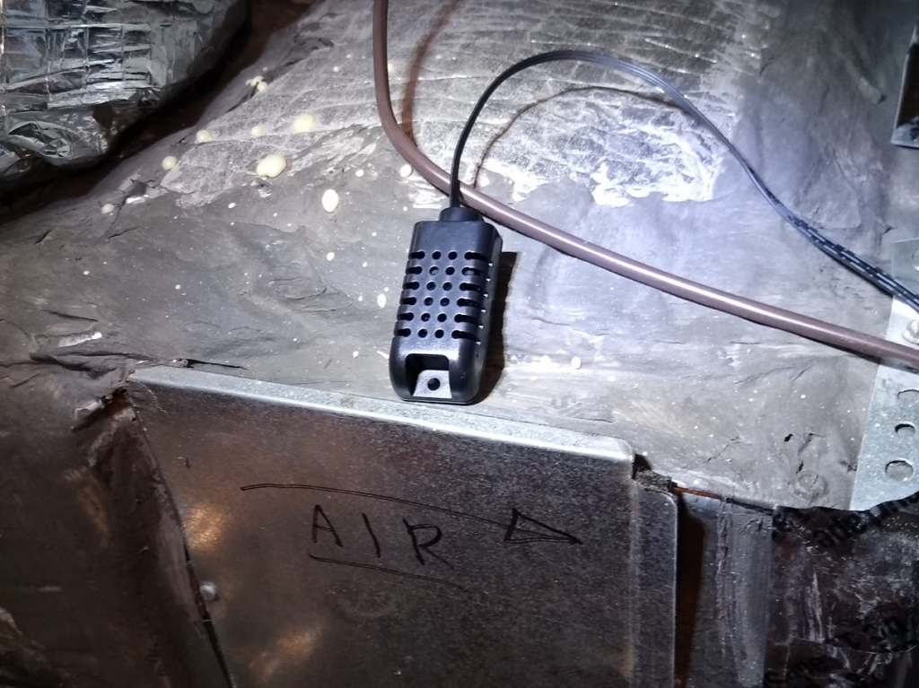
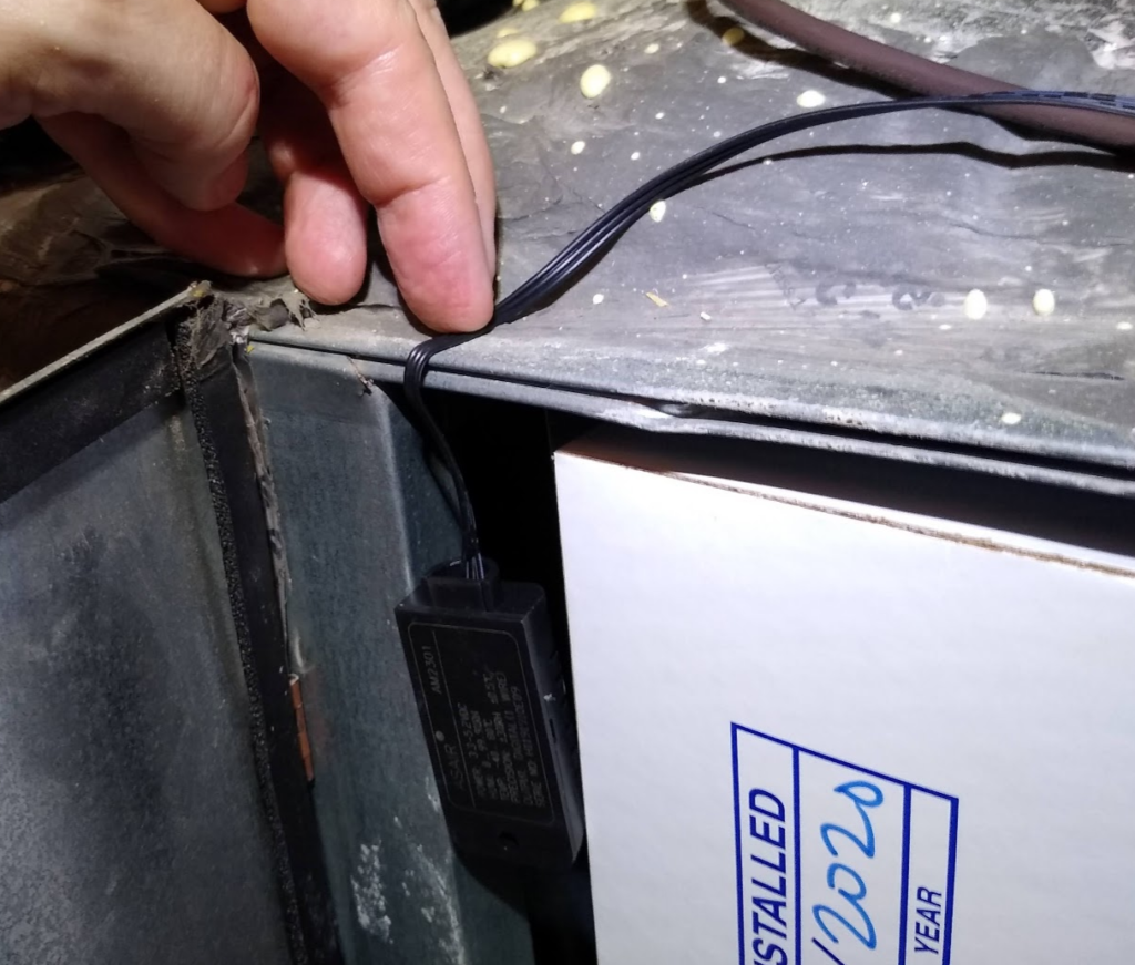
Simply close the air filter door, and for this installation, the inlet temperature/humidity sensor install is finished. After this probe was setup, the filter door was checked, while the unit was running, to see if there was any escaping air around the door seal. No escaping airflow could be detected.
The last sensor to install is the water rope leak detection sensor. This sensor comes with a 10-foot wire leader, and then 5 feet of water rope. This is so the sensor can be plugged into a node located up to ten feet away (high on a wall for example), and the water rope is put on the floor where a leak is likely to occur. In this case, the node and the water rope are located close together. Install the water rope sensor so it is in the lowest area of the air conditioner water collection pan, and is just in front of the drain. Before installing the water rope, straighten out the plastic rope as much as possible so it will lay flat. Tape the water rope in place with some of the foil tape. Always clean the surface for taping with alcohol before applying the tape. It is a good idea to locate the junction of the wire leader and the water rope outside of the drip pan where it will not get wet.
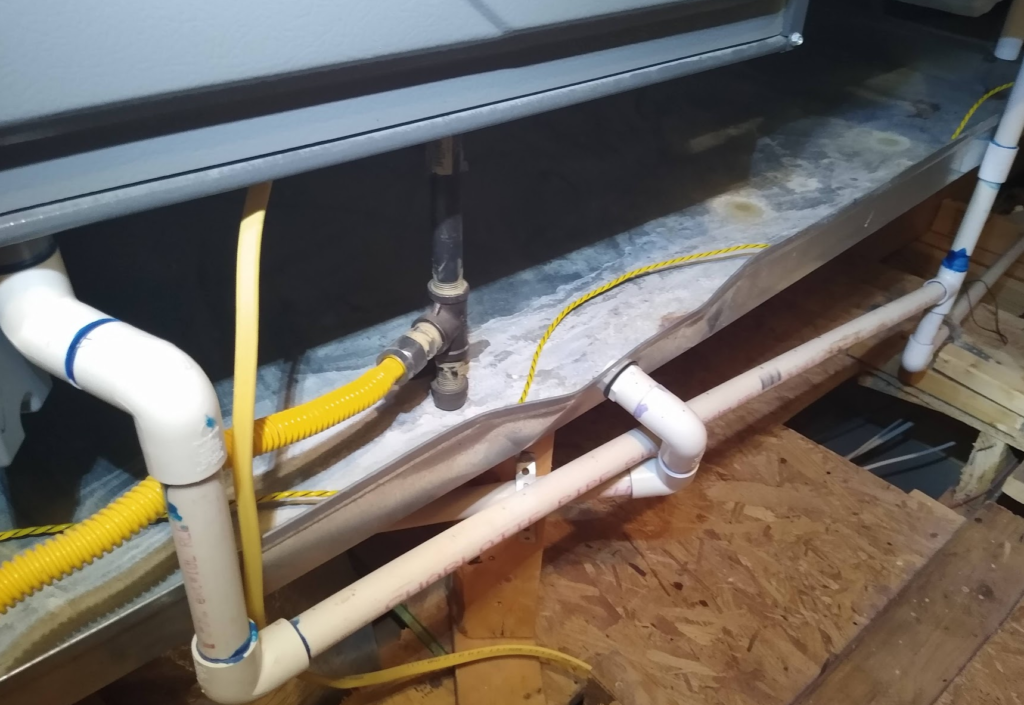

The two pictures below show the final location of the SN400 sensor node with all the sensor wires installed. It is attached to the air conditioner evaporator.
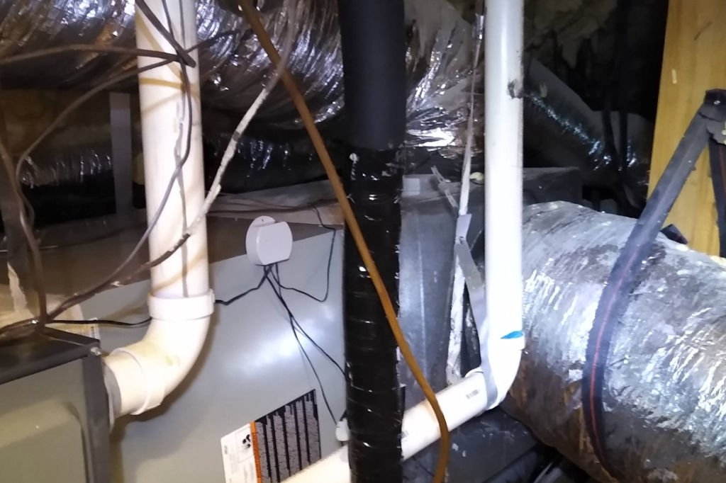
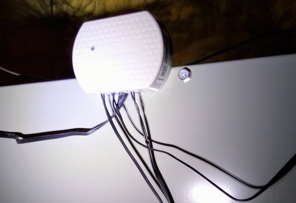
The SN400 sensor node and sensors installation is now complete. The air-conditioner parameters can be monitored in the R9 web-browser dashboard. This paper will not discuss operation of the web browser based R9 portal. Please refer to the R9 Portal User Guide located online for information on how to operate the portal features (located online under Resource, Documentation).
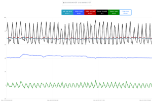
The portal dashboard setup is shown in the image below. The top line is information for the gateway, and the bottom line is information for the sensor node that is attached to the air conditioning unit. The bottom line shows all 6 sensor channels and the last recorded value. The R9 system records and will display sensor data on charts using a 15 minute interval.

The image below shows a picture of the chart display with all the sensor channels enabled. This is a 7 day period from August 3rd to August 10th , when the outside temperature was hot, getting up to 100F in the afternoon. The colors in the chart below represent:
-
-
- Aqua = AC unit ambient temperature
- Green = Input temperature
- Black = Input humidity
- Red = Output temperature (downstairs)
- Blue = Output temperature (upstairs)
- Brown = water leak sensor (100 = dry, 0 = wet, 50= not connected)
-
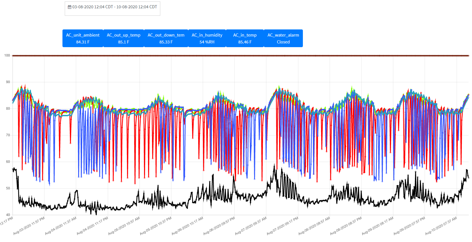
The temperature is getting warmer during the daytime, ambient attic temperature is ~ 85F during the day. This is partially caused by the warmer attic temperature, but also because the AC unit itself is set to 82F during the daytime. The attic ambient temperature is actually relatively cool because this building uses a “sealed attic” form of spray in foam insulation. This means that the attic will stay close to the house ambient temperature, even though it is not directly cooled with an AC outlet duct.
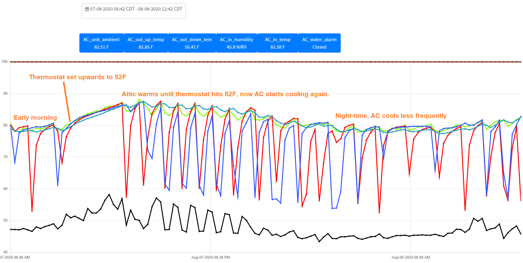
The image below is a two-day portion of the image above. It is easier to view the chart details in the image below.
So how do you determine the operating status and health of your AC system?
-
-
- The water rope will capture leak events directly.
- The temperature difference between input air, and output air, tells you how well the AC system is cooling.
-
In the chart above it can be seen that under normal conditions, the AC unit cools the incoming air by about 25 degrees F. The exact number will depend on several environmental factors, but temperature difference for this unit indicates about 25F all summer long. In the heat of the day, with warmer input air, the output air is about 60F. At night, the output air will get down below 55F. This baseline operation can be scanned and shows a “healthy” air conditioner unit. If, for example, the AC refrigerant is slowly leaking, the AC unit will run for a longer period, and the temperature differential will be much less, maybe 10 degrees F (still cooling, but very inefficient). If the freon has leaked out completely, or the outdoor compressor is not turning on, you will see no temperature differential (between the input and output air temperatures).
So how would you setup SMS and email alerts to monitor your AC system cooling effectiveness?
-
-
- The water rope alert can be enabled to send you an alert directly if it ever detects water. There is a filter setting (allowable error settings) that defaults to two. This means the system has to get three consecutive, 15-minute samples of wet before an alert is sent.
- The air conditioner output temperature (upstairs) can be directly monitored. This temperature channel should have an allowable range of below 60F alert set-up. An allowable error setting of 80 would also be set. This means that the R9 monitor has to see the air conditioner output temperature go below 60F at-least once in a 20-hour period. If this does not happen (for example, due to low refrigerant), an error alert is sent to the user. This alert type will have to be modified or turned off during the winter time. A simpler, but less direct, measurement alternative is outlined below.
-
There are many ways the alerts can be set-up. Please refer to the application note titled “R9 Safezone – How to Configure Accurate Temperature Alerts” for more information on setting temperature alerts. This note applies to refrigeration, but the specifics on the setting of alerts is the same (located under the “Resources” and then “Documentation” webpage tabs on the R9 website). Note that furnace operation of the air conditioner has been omitted from this application note for brevity. All the same principles apply, and furnace operation can also be monitored.
A practical installation for remote property management would likely include several sensor nodes distributed through-out a building. So direct measurement of building temperatures can be used to set alerts. The sensor node mounted to the air conditioner is used to verify efficient operation of the cooling system, and to check for water leaks.
If other nodes were not available for directly measuring the building temperature, the input temperature/humidity sensor attached to the AC unit could be moved to below the attic floor. This would place the sensor in one of the air-conditioned rooms in the upper level. This would indirectly measure the AC input temperature, but is a more stable measurement of the ambient temperature of the building top level. An alert temperature operating range
of 65F to 83F can then be set, so an alert will be generated if the air-conditioned room temperature is ever outside this range. This is a “set and forget” type of alert, that is not affected by seasonal operation of the air conditioner or heater. When used in conjunction with the leak detect feature of the water rope, this setup (one sensor node) gives a simple and effective indication that the air conditioning of a building is operating properly. The two air conditioner outlet temperatures can also be checked, to verify the AC unit is operating efficiently.

